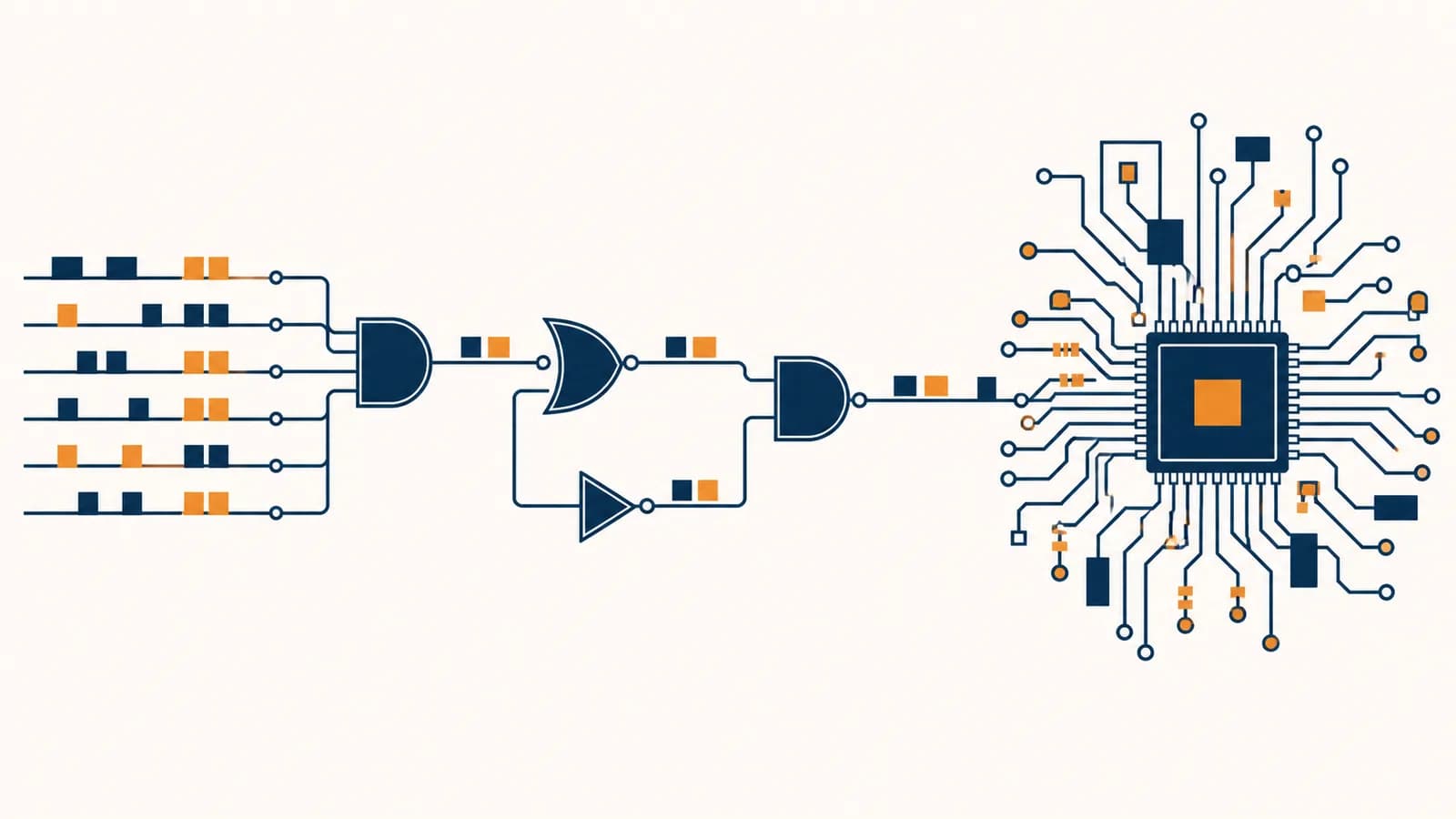
Binary logic is a two-state system that represents information and controls circuits through logical rules, in the context of computer hardware. Binary numbers encode values as bits, Boolean logic defines operations such as AND, OR, and NOT, logic gates perform those operations, and circuits connect gates to calculate, store, and control data. The idea exists because electronic devices can distinguish two voltage ranges reliably, even when heat, electrical noise, and manufacturing differences make exact voltages uncertain.
A computer does not think as a person does. It changes physical signals according to designed rules. Those changes can implement arithmetic, compare two values, select an instruction, save a bit, or light a pixel. Layers of encoding let the same two states stand for a number, a letter, an image, or a program instruction. The meaning comes from how hardware and software agree to interpret the bits.
What binary actually is
Binary is a base two number system that uses only the digits 0 and 1. Each position represents a power of two, so the value of a binary number is the sum of the powers whose positions contain a 1.
Decimal uses ten digits and place values of 1, 10, 100, and so on. Binary follows the same positional idea with place values of 1, 2, 4, 8, 16, and so on. Reading 1101 from right to left gives one 1, zero 2s, one 4, and one 8. Its decimal value is 13.
The subscript 2 identifies base two. Each step to the left doubles the place value.
A single binary digit is a bit. A group of eight bits is a byte. With one bit, there are two possible patterns. With two bits, there are four: 00, 01, 10, and 11. Each added bit doubles the number of available patterns, so bits can form patterns.
Those totals follow directly from exponentiation. They describe patterns, not automatically the largest represented number. If an unsigned eight-bit value starts at zero, its range ends at 255 because zero itself uses one of the 256 patterns. A signed format reserves a convention for negative values, which changes the range without changing the physical bits.
How bits represent numbers, text, sound, and color
Bits represent information through an agreed encoding: a rule that maps each bit pattern to a meaning. Hardware stores only patterns, while file formats, character standards, and programs decide whether a pattern means 65, the letter A, a sound sample, or a color.
Suppose a memory location contains 01000001. Interpreted as an unsigned binary integer, it is 65. Interpreted using the ASCII character code, it is the capital letter A. Nothing inside the byte announces which interpretation is correct. The instruction using the byte and the surrounding data format supply that context.
01000001 is a sequence of eight two-state values. It has no built-in label saying number, letter, sound, or instruction.
An encoding or processor instruction treats the pattern according to a defined rule. Under ASCII it is A; as an unsigned integer it is 65.
Images usually encode each pixel with numeric channel values. In a common 24-bit RGB representation, eight bits describe red, eight describe green, and eight describe blue. That gives 256 levels per channel and possible channel combinations. A specific file may also store transparency, color profiles, compression data, and other information.
Digital sound is a sequence of measured amplitude values taken at regular times. More bits per sample allow more possible amplitude levels. A higher sampling rate records values more often. Binary is not the sound itself; it is the notation used to store numbers that approximate a changing air pressure signal.
Bits carry patterns, not meaning. Meaning comes from a contract about how a program, file format, network protocol, or processor instruction interprets each pattern.
This distinction explains why opening a document in the wrong program can produce nonsense. The bits may be intact, but the program applies the wrong decoding rules. It also explains why database systems that organize stored data track types such as integer, text, date, and Boolean instead of treating every value as an unexplained byte sequence.
What Boolean logic actually is
Boolean logic is a system for combining values that are either true or false. Its operations produce another true or false value, which makes Boolean algebra a precise language for conditions in programs and for two-state signals in digital hardware.
The three basic operations are AND, OR, and NOT. AND is true only when both inputs are true. OR is true when at least one input is true. NOT reverses a single input. Hardware designers often write true and false as 1 and 0, but a truth value is a logical idea, while a bit is its physical or stored representation.
| A | B | A AND B | A OR B | A XOR B |
|---|---|---|---|---|
| 0 | 0 | 0 | 0 | 0 |
| 0 | 1 | 0 | 1 | 1 |
| 1 | 0 | 0 | 1 | 1 |
| 1 | 1 | 1 | 1 | 0 |
A truth table lists every possible input combination and the resulting output. XOR, meaning exclusive OR, is true when the inputs differ. It is useful in addition because the low bit of and is 1, while the low bit of and is 0.
A building access system might open a door when badgeValid AND doorScheduledOpen AND NOT alarmActive is true. The sentence can be tested as Boolean logic, then implemented in software, hardware, or both.
Long expressions can be simplified with Boolean algebra. For example, . If A is already required, adding the choice between A and B changes nothing. Simplification can reduce the number of gates, chip area, energy use, and delay in a circuit.
How logic gates work
A logic gate is a circuit that maps one or more input voltage ranges to an output voltage range according to a Boolean rule. Gates restore signals toward recognized low or high levels, allowing many operations to connect without requiring perfect voltages.
Inside a modern digital chip, gates are commonly built from transistors. A transistor acts as an electrically controlled path. In complementary metal oxide semiconductor logic, usually shortened to CMOS, networks of two transistor types pull an output toward the supply voltage or toward ground. The network arrangement determines the logical function.
A low input lies inside the circuit's accepted low range. A high input lies inside its accepted high range. Values between guaranteed ranges may not be interpreted reliably.
Each input voltage changes which transistor paths conduct. The arrangement creates a path toward the supply, a path toward ground, or a temporary transition between them.
Charge moves into or out of the output node. Its voltage rises or falls rather than changing instantaneously.
After a propagation delay, the output settles into a range that another gate recognizes as low or high.
A simple CMOS NOT gate, also called an inverter, uses one transistor network to pull the output high when the input is low and another to pull it low when the input is high. This physical mechanism creates the truth table for NOT. NAND, NOR, and more complex gates use larger networks.
Real gates have limits that ideal truth tables omit. Every transition takes time. Charging a larger electrical load takes longer. Transistors can leak current, and switching uses energy. Designers therefore check timing, fan-out, power, temperature, and noise margins as well as logical correctness.
Logic gates versus transistors
A transistor is a physical electronic device that controls current, while a logic gate is a functional circuit made from transistors and other connections. One describes a component; the other describes a Boolean behavior created by a group of components.
The difference resembles the difference between a valve and a plumbing control system. A valve controls a path, but several valves and pipes can implement a rule about when water flows. Likewise, transistor networks implement rules about an output signal. The analogy stops at the mechanism because charge, voltage, and semiconductor behavior are not literally water.
A semiconductor device with terminals whose electrical conditions affect conduction. Its behavior is analog and continuous, even when a digital design uses selected ranges.
A circuit abstraction with inputs, an output, and a Boolean rule. It hides most device physics so a designer can reason with truth tables and timing.
Digital design depends on layers of abstraction. A chip engineer can connect gates without recalculating semiconductor physics for each one. A processor designer can connect adders, registers, and control units without placing each transistor manually. A programmer can write an addition expression without choosing gates. Each layer is real, but each exposes only the details needed for its task.
Software still reaches the hardware through these layers. A language such as JavaScript may look far removed from transistor switching, yet its operations are eventually translated into processor instructions that manipulate encoded values.
How circuits add, choose, and remember
Digital circuits gain useful behavior by connecting gates into larger units. Combinational circuits produce outputs from current inputs, while sequential circuits also depend on stored state, which lets a computer calculate, select data, count steps, and remember previous events.
A half adder handles one binary column
A half adder adds two one-bit inputs. XOR produces the sum bit, and AND produces the carry bit. For inputs 1 and 1, XOR gives 0 and AND gives 1, so the two-bit result is 10, which is binary for two.
| A | B | Sum | Carry |
|---|---|---|---|
| 0 | 0 | 0 | 0 |
| 0 | 1 | 1 | 0 |
| 1 | 0 | 1 | 0 |
| 1 | 1 | 0 | 1 |
A full adder also accepts a carry from the previous column. Connecting full adders creates a multi-bit adder. To add 0111 and 0011, the rightmost columns generate carries that move left, producing 1010. In decimal, the visible check is .
A multiplexer chooses one input
A multiplexer is a controlled selector. Data inputs feed it, select bits name one input, and the circuit forwards that chosen value. Processors use multiplexers to decide which register, arithmetic result, memory value, or instruction address should travel along a shared path.
A latch or flip-flop stores state
Feedback lets a circuit retain information. In a feedback loop, an output influences later input to the same structure. A latch can hold one bit while an enable signal controls when it may change. A flip-flop commonly captures a bit at a clock transition, giving many parts of a circuit a shared schedule.
A clock does not make every operation instantaneous. It divides activity into timed intervals. Signals still need enough time to travel through gates and settle before the next state capture.
Registers group flip-flops to hold multi-bit values. Counters combine stored state with logic that computes the next value. Memory systems build much larger storage structures with different circuit designs. These stateful components are the bridge between a truth table that reacts now and a machine that follows a sequence.
How binary logic shows up in a processor
A processor repeatedly fetches an encoded instruction, decodes its bit fields, performs the requested operation, and records a result. Logic circuits coordinate data paths and state so billions of simple local signal changes can carry out a program's ordered instructions.
An instruction is a bit pattern divided into fields according to the processor's instruction set. One field can name an operation such as add. Other fields can name registers containing the inputs and destination. The control circuitry interprets those fields and activates paths that carry values through the arithmetic logic unit.
Consider an instruction that adds the contents of two registers. The decoder recognizes the operation code. Multiplexers route the selected register values to an adder. The adder produces a result and status signals, such as whether the result was zero. At a controlled time, the destination register captures the new bits.
Pressing a key changes a signal detected by an input controller. Software receives an encoded key event, updates text data, asks a graphics system to draw a glyph, and changes pixel values in a display buffer. Each layer uses binary representations, but each assigns them a different meaning.
A processor also needs memory, input and output controllers, and software that assigns work. How an operating system manages hardware explains the layer that schedules programs, protects memory, and coordinates devices above these circuits.
Modern processors improve performance with caches, pipelines, parallel execution, prediction, and specialized units. These features complicate the path, but they do not remove Boolean logic. They arrange far more combinational and sequential circuits so several useful operations can be in progress at once.
How binary logic shows up in daily devices
Binary logic appears wherever a digital device senses conditions, applies rules, stores state, or controls an output. A washing machine, car, router, game controller, medical monitor, and payment terminal all turn physical events into encoded signals and decisions.
A thermostat offers a compact example. A sensor produces an electrical measurement related to temperature. Conversion hardware turns that measurement into a number. Control software compares it with a target and checks modes, timers, and safety conditions. Output circuitry then switches heating or cooling equipment through an appropriate driver.
The first and last stages are often analog. Temperature, pressure, light, and sound vary continuously. Sensors, converters, and output drivers connect those quantities to digital processing. This is why saying that a whole device is only zeros and ones misses much of its engineering. Binary logic occupies the decision and representation layer between physical interfaces.
Networks add another setting. A device represents a message as bits, divides it according to protocol rules, and sends physical signals over radio, copper, or fiber. Receiving circuits recover bit values, check them, and pass decoded information upward. The detailed path appears in the explanation of packets, addresses, and Internet routing.
People who work directly with these ideas include digital hardware designers, embedded systems developers, computer architects, verification engineers, robotics engineers, network engineers, and repair technicians. A programmer may meet them while using bit masks, binary file formats, permissions, device registers, cryptographic operations, or performance tools.
Four mistakes people make with binary logic
Most confusion comes from collapsing several layers into one: number notation, logical truth, voltage, and human meaning. Keeping those layers separate prevents the common mistakes that computers literally understand symbols, that 1 always means on, or that digital signals are physically perfect.
1. Treating binary as a secret machine language
Binary is a number system and a family of two-state encodings, not one universal vocabulary. The pattern 1000001 can represent 65, a character code, part of an instruction, a color channel value, or a fragment of compressed data. A specification supplies the meaning.
2. Assuming 1 always means electricity is on
Designers map logical values to physical states. In active-high logic, a higher voltage usually represents 1. In an active-low signal, the asserted condition is represented by a low level. Storage technologies may use charge, magnetization, resistance, or other measurable states. The representation is chosen, not dictated by the symbol.
3. Imagining digital voltage as exactly zero or one
The symbols 0 and 1 describe accepted ranges and logical states. A physical voltage can contain noise, shift with load, and take time to change. Circuit specifications define which ranges are guaranteed to count as low or high. Noise margin gives ordinary disturbances room without changing the interpreted bit.
4. Believing more bits always make a device faster
Bit width affects what a circuit can represent or process in one operation, but speed also depends on clock timing, circuit design, memory delay, available parallel work, and software. A wider value can even require more circuitry and data movement. Width and speed answer different questions.
The quote is a summary, not an attribution. Engineers spend much of their effort ensuring that signals which look simple at the logical level remain distinguishable under real operating conditions. Abstraction hides that work from users, but it does not eliminate it.
How binary logic detects and contains errors
Digital systems detect some errors by adding redundant bits whose expected values can be checked later. They contain other errors through voltage margins, clock timing rules, repeated transmission, and circuit designs that keep a small disturbance from becoming a valid but wrong result.
An even parity bit is a basic example. The sender chooses an extra bit so the complete group contains an even number of 1s. If 1011001 contains four 1s, its even parity bit is 0. If one bit flips during transmission, the receiver counts an odd number and knows something changed.
For even parity, XOR of all data bits produces the parity bit. Checking all received bits should then produce 0.
Parity cannot locate the bad bit, and two flipped bits can escape detection because parity returns to even. More capable error-detecting codes use carefully chosen redundant patterns. Some error-correcting codes can identify and repair limited errors. The same design principle remains: extra structure lets a receiver distinguish at least some corrupted patterns from allowed ones.
Binary also helps at the electrical level because two broad valid ranges tolerate variation better than many tightly packed levels would. This does not make digital systems immune to faults. Radiation, defective components, poor timing, unstable power, software bugs, and damaged storage can still corrupt results. Engineers combine physical margins, logical checks, testing, and redundancy according to the cost of failure.
Binary computers versus quantum computers
A classical bit is read as one of two values, while a quantum bit is described by a quantum state that can produce different classical outcomes when measured. Quantum computing changes how selected algorithms are carried out, but it does not make ordinary binary systems obsolete.
A qubit is not simply a classical bit that holds 0 and 1 at the same time in the everyday sense. Before measurement, its state can be a weighted quantum combination of basis states, with relative phase affecting later interference. Measurement returns a classical outcome, and repeated runs reveal a probability distribution.
Gates map definite bit patterns to definite bit patterns. Engineers can copy ordinary bits, reset them, inspect them, and use error correction designed for classical states.
Quantum gates transform amplitudes while preserving quantum rules. Measurement changes what can be observed, unknown states cannot be copied freely, and error handling requires different techniques.
Quantum processors are suited to particular problem structures, not every calculation. They also depend on classical electronics and computers for control signals, compilation, measurement, and the rest of an application. A phone interface, database query, and thermostat controller still fit classical binary logic well.
What 32-bit and 64-bit actually describe
Terms such as 32-bit and 64-bit usually describe a width used by a processor architecture, commonly the size of general-purpose registers, integer operations, or memory addresses. The exact meaning depends on the architecture and is not a universal measure of quality.
A register width tells how many bits a register holds. An unsigned 32-bit register has possible patterns, while an unsigned 64-bit register has . Signed integer conventions allocate those same patterns across negative and nonnegative values. The processor documentation defines which operations use each width.
Address width concerns how memory locations are named. A theoretical -bit byte address has possible address patterns, but an actual machine may implement fewer address bits and support less physical memory. Operating system limits, chip design, and device layout also constrain what can be used.
64-bit does not mean every piece of data occupies 64 bits. Programs still use bytes, narrower integers, wider vectors, character encodings, and data structures chosen for the task.
Bit width matters because it shapes instruction formats, numeric ranges, memory addressing, data movement, and compatibility. It says little by itself about clock speed, battery life, processor workload, or program quality.
Binary logic connects software to physical machines
Binary logic gives Computer Science a precise bridge between symbolic instructions and electronic behavior. Bits encode choices, gates apply rules, circuits combine and store results, and layered systems turn those results into useful actions in the physical world.
The next time a device reacts, trace one action backward. A pixel changed because a stored color value changed. That value changed because an instruction wrote it. The instruction moved through control circuits, registers, and gates. Those gates changed voltage and charge through transistor networks.
Then trace the action forward from a physical input. A button closes a contact or changes a sensed voltage. Interface hardware produces a stable digital event. Software interprets the event according to an encoding and updates state. Output circuits finally change light, sound, motion, or a transmitted signal.
The takeaway: Do not stop at “computers use zeros and ones.” Ask what each pattern represents, which logical rule transforms it, how a circuit implements that rule, and what physical event enters or leaves the system.