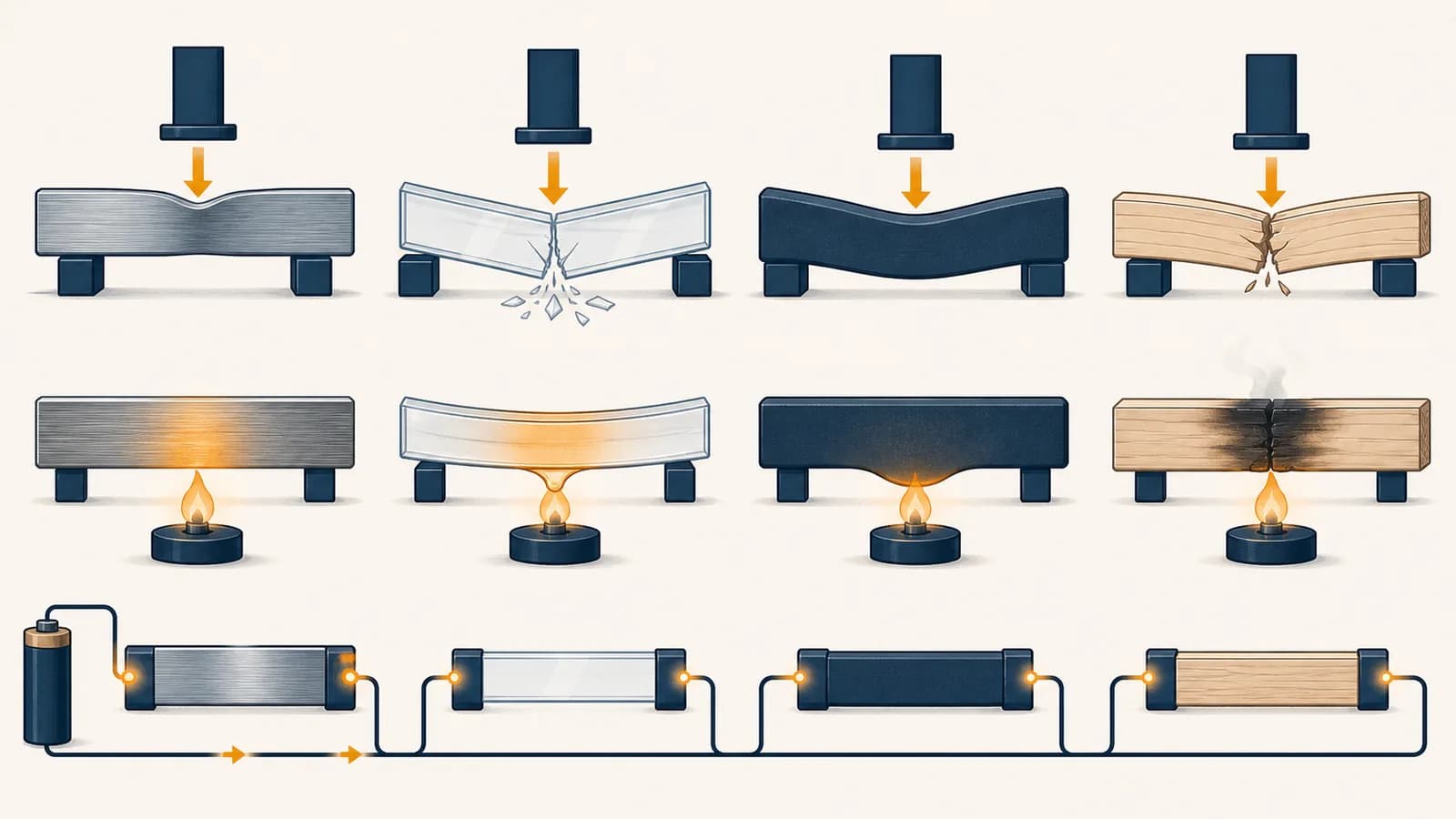
Materials and Properties is a field of physics that explains how substances respond to forces, heat, electric fields and their surroundings. Material properties include physical properties such as density and conductivity, and mechanical properties such as strength, stiffness, hardness, toughness and elasticity. These ideas exist so that people can predict what an object will do before they build it, load it, heat it or send current through it. A bicycle frame, phone screen, bridge cable and cooking pan can have similar shapes yet behave very differently because their internal structures and properties differ.
What a material property actually is
A material property is a measurable response that belongs to a specified sample under stated conditions, rather than to the object’s size or shape. It lets people compare substances and calculate how each one is likely to behave in use.
A steel wire can be long or short, thin or thick. Those dimensions change how much load the wire can carry and how far it stretches, but they do not by themselves change the kind of steel. A property removes as much of the geometry as possible. Density compares mass with volume. Stress compares force with cross sectional area. Strain compares a change in length with the original length.
Properties fall into several useful families. Mechanical properties describe responses to pushes, pulls, impacts and repeated loads. Thermal properties describe heat flow, heat storage and expansion. Electrical properties describe how charges move or become displaced. Optical, magnetic and chemical properties cover other interactions.
A reported property is incomplete without conditions. Temperature can change stiffness and electrical resistance. Grain direction can make wood stronger along the grain than across it. Heat treatment can give two pieces with the same chemical composition different hardness. Test speed, moisture and manufacturing history may also matter.
A property is not a permanent label. “Strong,” “conductive” or “brittle” only becomes useful when the loading direction, temperature, test method and relevant threshold are clear.
This is why engineers use agreed test procedures and identify the material grade, condition and orientation. A number in a table is a starting point. The actual component must still be checked in the state in which it will work.
How forces change a material
A force changes the spacing or arrangement of particles inside a material. Small changes may reverse when the force is removed, while larger changes can leave permanent deformation, start a crack or separate the material into pieces.
Solids feel rigid because their atoms or molecules occupy stable arrangements. The particles are not motionless, and they are not connected by tiny literal springs. Electromagnetic interactions make some separations energetically favourable. Pulling a solid slightly farther apart or pushing it slightly closer together requires force, much as moving a ball away from the bottom of a curved bowl requires work.
The force pattern matters. Tension pulls material apart. Compression pushes it together. Shear makes neighbouring layers slide. Torsion twists a member, producing shear within it. Bending puts one side into tension and the other into compression. A beam can therefore fail on one face even though the force was applied somewhere else.
For a modest load, many solids deform elastically. Their particles shift a little, and internal forces restore the original arrangement after unloading. Beyond an elastic limit, some materials deform plastically. Crystal defects move, molecular chains slide or microscopic structures rearrange, so the original shape is not fully recovered.
Bend a metal paper clip slightly and it springs back. Bend it farther and it stays bent. Repeat the large bend at the same spot and a crack grows until the clip breaks. The same object has shown elasticity, plasticity and fatigue failure.
The motion of an entire object is handled through the force laws in how forces produce acceleration. Materials physics asks the next question: how are those forces distributed inside the object, and what does that distribution do to its shape and structure?
How stress and strain turn loads into comparable quantities
Stress measures internal force intensity, while strain measures relative deformation. Dividing force by area and extension by original length allows fair comparisons between specimens whose dimensions differ, and links a laboratory test to a full sized component.
A thick cable can carry more force than a thin cable made from the same material because more material shares the load. Force alone therefore does not identify the material’s condition. For a straight member under a uniform tensile load, engineering stress is force divided by original cross sectional area.
A force of 10,000 N spread over 0.0001 m² produces 100,000,000 Pa, or 100 MPa, because 10,000 ÷ 0.0001 = 100,000,000.
The pascal is one newton per square metre. Engineering materials often experience stresses of millions of pascals, so megapascals, written MPa, are convenient. The calculation above is visible arithmetic, not a measured claim about a particular alloy.
Extension also needs context. A 1 mm stretch is large for a 10 mm sample but small for a 10 m cable. Engineering strain divides the change in length by the original length, so it has no unit.
If a 2.00 m rod becomes 2.01 m long, its strain is 0.01 ÷ 2.00 = 0.005, which is 0.5%.
A tensile test records force and extension as a machine pulls a standard specimen. Converting those measurements to stress and strain produces a curve. Its early slope indicates stiffness. Departure from elastic behaviour marks yielding. Its highest engineering stress is the ultimate tensile strength. The final point records fracture, although the exact definitions used in reports follow the relevant testing standard.
Record gauge length and cross sectional dimensions so force and extension can be normalised.
Pull the specimen while sensors record force and extension at many points.
Divide each force reading by area and each extension reading by original gauge length.
Identify elastic response, yield behaviour, maximum stress and fracture strain.
Real stress fields are often not uniform. A hole, sharp corner or scratch can concentrate stress locally. Computer models and strain gauges help reveal those concentrations, but test pieces remain useful because they show how a real material responds, including defects that an ideal model may omit.
Stiffness versus strength
Stiffness is resistance to elastic shape change, while strength is the stress a material tolerates before a chosen form of failure. A material can be stiff but relatively weak, or flexible yet able to survive high stress.
In the linear elastic region of a tensile test, many materials approximately follow Hooke’s law: stress is proportional to strain. The proportionality constant is Young’s modulus, written . A larger modulus means more stress is needed to produce the same elastic strain.
If 100 MPa of stress produces a strain of 0.0005, then E = 100 MPa ÷ 0.0005 = 200,000 MPa, or 200 GPa.
Strength requires a named limit. Yield strength concerns the onset of specified permanent deformation. Ultimate tensile strength is the maximum engineering stress reached in a tensile test. Compressive strength and shear strength refer to different loading modes. None is interchangeable with Young’s modulus.
Shows little elastic strain under a given stress. A glass pane is stiff because it barely changes shape before failure.
Withstands a high specified stress before yielding or breaking. Strength says where a limit lies, not how much earlier elastic movement occurs.
Geometry creates another distinction. Material stiffness is represented by a modulus. Structural stiffness describes a component and depends on both material and shape. A steel ruler bends easily about its thin direction but resists bending about its wide direction. The steel has not changed, only the cross section’s orientation has.
Hardness is different again. It measures resistance to a local indentation, scratch or related surface deformation under a defined test. Hardness can correlate with tensile strength within some material families, but it is not strength itself. A coating may have a hard surface while the material underneath remains soft and able to bend.
How failure works
Failure begins when a material can no longer perform its required function, which may happen through yielding, fracture, buckling, fatigue, creep or wear. Breaking into two pieces is only the most visible of several possible failure modes.
Ductile failure involves substantial plastic deformation before fracture. It often gives warning through stretching, bending or necking. Brittle fracture involves little large scale plastic deformation and can spread rapidly once a crack becomes unstable. Loading rate, temperature, thickness and existing flaws can shift the observed behaviour.
Toughness describes the energy a material absorbs per unit volume before fracture in a specified test. On a stress strain graph, it corresponds to the area under the curve up to fracture. A strong material that breaks at tiny strain may be less tough than a moderately strong material that deforms greatly before breaking.
A hard surface resists local indentation, yet an existing crack may still grow with little plastic blunting. Some ceramics show this combination.
Plastic deformation around a crack consumes energy and can slow its growth. Many structural metals are selected partly for this behaviour.
Cracks change the local stress. At a sharp crack tip, forces are concentrated into a very small region. Atomic bonds there can separate even while the average stress across the component looks acceptable. Fracture mechanics studies this interaction among applied load, crack size, component geometry and resistance to crack growth.
Repeated loading introduces fatigue. A stress cycle can advance a small crack by a tiny amount. After enough cycles, the remaining intact section may be too small to carry the load and it fractures. The peak stress can be below the stress that would break an undamaged sample in one pull. Rotating shafts, aircraft structures and bicycle components are therefore inspected for cracks, not only for obvious bending.
A steady load can also cause slow permanent deformation called creep, especially when temperature is high relative to the material’s melting temperature. Turbine parts, hot pipes and polymer components may gradually change shape over time. Wear removes or rearranges surface material through contact and motion. Buckling is a structural instability in which a slender compressed member bends sideways, sometimes before its material reaches compressive failure stress.
Failure is defined by the job. A beam that deflects enough to jam a door has failed in service even if it has not cracked, yielded or collapsed.
Energy is the common thread through impact, fracture and deformation. A moving object can damage a material because its kinetic energy is transferred into elastic energy, plastic deformation, heat and the creation of new crack surfaces.
How structure controls properties
A material’s properties emerge from its particles, bonds, phases, defects and larger scale arrangement. Chemical composition matters, but the same ingredients can behave differently when processing changes crystal structure, grain size, porosity, fibre direction or molecular alignment.
At the atomic scale, bonding influences stiffness, thermal expansion and conductivity. Strongly curved energy relationships near the equilibrium particle spacing tend to produce high stiffness. Mobile electrons allow metals to conduct electric current and thermal energy. In insulators, charges are more tightly bound, although an electric field can still shift them slightly and polarise the material.
Crystalline solids arrange atoms in repeating patterns. Real crystals contain vacancies, impurities, grain boundaries and line defects called dislocations. Plastic deformation in many metals occurs largely because dislocations move through the lattice. Obstacles that hinder their motion can raise yield strength, although the change may reduce ductility.
This sequence explains why manufacturing is part of materials physics. Cooling a metal at different rates can change which phases form. Cold working can increase dislocation density and make further plastic movement harder. Heating after deformation can allow recovery or recrystallisation. In polymers, stretching during manufacture can align long molecular chains and make the final product direction dependent.
Composite materials deliberately combine unlike constituents. Reinforcing fibres may carry much of a tensile load while a surrounding matrix keeps the fibres aligned, transfers stress and shields them from damage. Direction matters: a fibre composite can be very stiff and strong along its fibres but much less capable across them. Plywood alternates wood grain direction to reduce the extreme directional behaviour of a single board.
Porosity usually lowers density, but pores can also concentrate stress and reduce load bearing area. Controlled pores are useful in foam insulation because trapped gas restricts heat transfer. The same feature that improves thermal performance may lower mechanical strength. Material selection therefore involves linked tradeoffs, not a single ranking.
How material properties show up in engineering design
Engineering design turns a required function into property limits, then checks candidate materials together with shape, processing, environment, cost and safety. The best choice is the material system that meets the full set of constraints, not the one with the highest headline value.
Consider a reusable drink bottle. Its wall must resist internal pressure and dents, remain acceptably light, tolerate cleaning temperatures and avoid unwanted chemical interaction with the contents. The cap needs enough stiffness to seal and enough toughness to survive drops. A transparent bottle adds optical transmission to the requirements. No single property decides the design.
State what the part must do and what would count as unacceptable leakage, deformation, wear, fracture or overheating.
Estimate forces, pressures, temperatures, cycles, impact energies and environmental exposure.
Specify limits for strength, stiffness, density, conductivity, toughness or other relevant responses.
Change thickness, cross section, joints and processing because geometry and manufacture affect component performance.
Check prototypes and production samples under realistic conditions, including damage and variation.
A safety factor compares a failure threshold with the expected working demand, but it is not permission to ignore the failure mechanism. Uncertain loads, variable material quality and severe consequences may justify a larger margin. Fatigue, corrosion or creep can require a life calculation rather than a simple division of strength by working stress.
A phone screen needs hardness to resist scratching, stiffness to preserve its shape, optical clarity for the display and fracture resistance for drops. Increasing surface hardness alone cannot guarantee survival, because an impact can drive a crack from an edge flaw. Case design changes the load path and can matter as much as the glass composition.
Architects and civil engineers also design load paths. A concrete column uses concrete effectively in compression, while embedded steel reinforcement carries tension and helps control cracking. The composite works because the materials share load and have compatible roles. Inspection remains necessary because water, salts, heat and repeated traffic can change the system over time.
Material choices also appear in law and evidence. Product standards may prescribe test methods or minimum performance. Failure investigators inspect fracture surfaces, deformation, corrosion, manufacturing records and service loads to reconstruct what happened. A broken part is physical evidence of forces and structural changes, not simply proof that the material was “bad.”
What density and conductivity actually tell you
Density tells how much mass occupies a unit volume, while conductivity tells how readily a material transports electric charge or thermal energy under specified conditions. Neither value directly states strength, quality or suitability for a particular product.
Density is . If a solid block has a mass of 2.4 kg and a volume of 0.0008 m³, its density is 3,000 kg/m³. Doubling every dimension multiplies volume and mass by eight, so the density stays the same if the material contains the same structure and porosity.
A panel with density 600 kg/m³ and volume 0.020 m³ has mass 600 × 0.020 = 12 kg.
Low density helps when mass must be moved, but stiffness and strength must be considered beside it. Designers often compare property per unit density, called a specific property. A low density material can justify a thicker shape, and that greater thickness may improve bending stiffness. The correct comparison is between complete designs that meet the same function.
Electrical conductivity describes current density produced by an electric field. Resistivity is its reciprocal for an isotropic material. A wire’s resistance also depends on its length and cross sectional area, so conductivity is a material property while resistance is a property of the actual conductor. Thermal conductivity similarly describes heat transfer through a material under a temperature gradient.
Resistivity belongs to a specified material at stated conditions and is expressed using geometry independent units.
Resistance depends on resistivity, length and area. A longer wire has more resistance, while a thicker wire has less.
Optical properties follow a similar pattern. Transparency is not a guarantee that every wavelength passes equally, and surface finish can change reflection and scattering. The interaction of light with matter connects material choice to lenses, coatings and displays, topics developed through light, reflection and wave behaviour.
How temperature changes material properties
Temperature changes particle motion, spacing, phase and transport processes, so it can alter dimensions, stiffness, strength, toughness, conductivity and electrical resistance. A property measured at room temperature cannot automatically be used for a hot engine or a cold outdoor structure.
Most materials expand when heated because their average particle separation increases. For a modest temperature range, linear expansion is often approximated by , where is the coefficient of linear expansion. The coefficient depends on the material and may itself vary with temperature.
If a 2.0 m member has α = 12 × 10⁻⁶ per °C and warms by 50 °C, the calculated expansion is 12 × 10⁻⁶ × 2.0 × 50 = 0.0012 m, or 1.2 mm.
The example coefficient is an assumed value for arithmetic, not a claim about an unnamed material. In actual design, the coefficient comes from a traceable specification for the material and temperature interval. Expansion joints in bridges and gaps around rails or pipes allow movement without forcing large thermal stresses into constrained structures.
Temperature can also change failure mode. Some materials become more ductile as temperature rises, while others soften, creep or lose useful strength. Some metals can show a transition toward more brittle fracture as temperature falls. Polymers may pass through a glass transition, changing from relatively hard and glassy behaviour to softer, more mobile molecular behaviour over a temperature region.
Daily example: A pan handle must limit heat flow to the hand, tolerate repeated heating and keep enough stiffness to support the pan. Low thermal conductivity alone is not a complete specification.
Phase changes can dominate the response. Melting destroys the shear rigidity of an ordinary solid, while freezing can create expansion or internal stresses in water filled pores. Heat treatment uses controlled temperature and time to change phase distribution and microstructure without changing the overall component shape very much.
5 mistakes people make with material properties
Most errors come from treating a single property word or table value as a complete prediction. Reliable reasoning names the property, units, conditions, loading mode, geometry and failure criterion, then checks how those pieces interact in the real component.
1. Calling every resistance “strength”
Strength is not an all purpose synonym for stiffness, hardness or toughness. A stiff item resists elastic deformation, a hard surface resists local indentation, and a tough material absorbs energy before fracture. State the response you mean and the test that measures it.
2. Ignoring shape and size
A material property alone does not tell how much load an object carries. Cross sectional area changes stress under an axial force. Beam depth strongly affects bending. Length affects extension and electrical resistance. Compare components only after accounting for geometry.
3. Assuming “elastic” means easy to stretch
Elastic means a deformation is recovered after unloading, within the relevant range. It does not mean the material is flexible. A steel spring and a rubber band can both return to their shapes, but their stiffness and strain ranges are very different.
4. Treating averages as local reality
Average stress can hide a severe concentration at a hole, notch, thread or crack. Average temperature can hide a hot spot. A component often begins to fail where the local condition is worst, so transitions and defects deserve attention.
5. Choosing the highest number
A higher property value is not automatically better. High thermal conductivity helps a heat sink but harms an insulated handle. High stiffness limits deflection but may come with density, processing or fracture tradeoffs. Selection begins with the job and its limits.
The takeaway: Replace vague labels with a full statement: this material, in this condition and direction, responds to this load or field by this measured amount.
Materials connect microscopic physics to visible behaviour
Materials physics connects forces and energy at particle scale to bending, conduction, fracture and wear at human scale. It becomes useful when you trace a visible response backward through geometry and structure to the interaction that produced it.
Every material object offers a small investigation. Notice where a spoon becomes hot, where a shoe sole wears, why packaging bends along a crease, or why a crack turns at an interface. Name the load, identify the relevant property and ask what internal structure could explain the response.
The subject also shows why physics cannot stop at ideal particles and perfectly rigid bodies. Real objects deform, dissipate energy and carry histories of manufacture and use. See how these ideas fit into physics as a whole for the force, energy, electricity and wave models that materials bring together.
Try the method on one object within reach. Separate the object’s geometry from its material, list two properties its job demands, then predict the first likely failure mode. That move, from an adjective such as “strong” to a mechanism you can test, is materials physics in practice.